Professional Drywall Repair in Aurora, CO
Installing a Floor-Warming System
This is an excerpt from the Book called “The Complete Guide To Bathrooms” by Black & Decker. Continue reading to learn more about Installing a Floor-Warming System, thanks to the author.
Floor-warming systems require very little energy to run and are designed to heat ceramic tile floors only; they generally are not used as sole heat sources for rooms.
A typical floor-warming system consists of one or more thin mats containing electric resistance wires that heat up when energized, like an electric resistance wires that heat up when energized, like an electric blanket. The mats are installed beneath the tile and are hardwired to a 120-volt GFCI circuit. A thermostat controls the temperature, and a timer turns the system on or off automatically.
The system shown in this project includes two plastic mesh mats, each with its own power lead that is wired directly to the thermostat. The mats are laid over a concrete floor and then covered with thin-set adhesive and ceramic tile. If you have a wood subfloor, install cement-board before laying the mats.
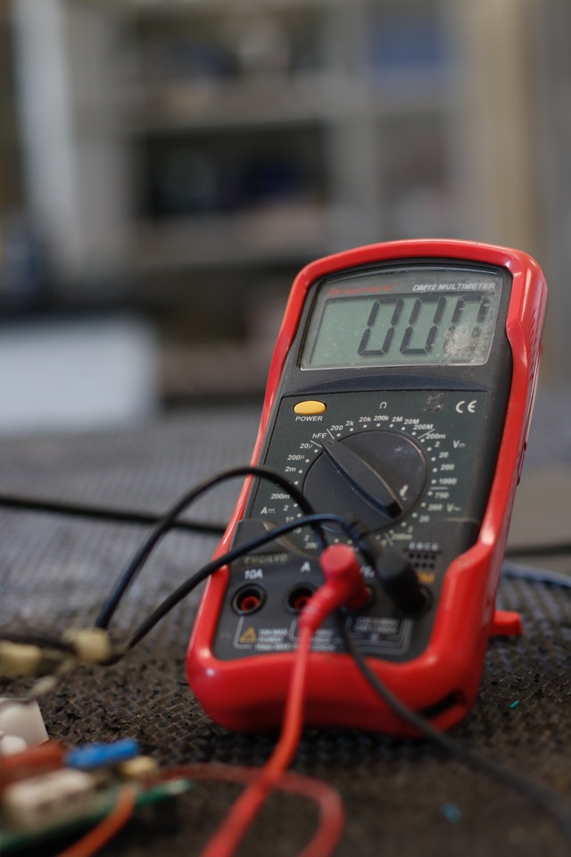
A crucial part of installing this system is to perform several resistance checks to make sure the heating wires have not been damaged during shipping or during the installation.
Electrical service required for a floor-warming system is based on size. A smaller system may connect to an existing GFCI circuit, but a larger one will need a dedicated circuit follow the manufacturer’s requirements.
To order a floor-warming system, contact the manufacturer or dealer. In most cases, you can send them plans and they’ll custom-fit a system for your project area.
Floor-warming systems must be installed on a circuit with adequate amperage and a GFCI breaker (some systems have built-in GFCIs) Smaller systems may tie into an existing circuit but larger ones need a dedicated circuit. Follow local building and electrical codes that apply to your project.
- Check the resistance value (ohms) of each heating mat, using a digital multi-tester. Record the reading. Compare your reading to the factory-tested reading noted by the manufacturer—your reading must fall within the acceptable range determined by the manufacturer. If it does not, the mat has been damaged and should not be installed; contact the manufacturer for assistance.
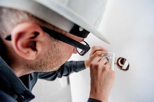
- Install electrical boxes for the thermostat and timer at an accessible location. Remove the wall surface to expose the framing, then locate the boxes approximately 60” from the floor, making sure the power leads of the heating mats will reach the double-gang electrical box. Mount a 2 ½ “-deep x 4”-wide double-gang electrical box (for the thermostat) to the stud closest to the determined location, and a single-gang electrical box (for the timer) of the stud.
- Use a plumb bob to mark points on the bottom plate directly below the two knockouts on the thermostat box. At each mark, drill a ½” hole through the top of the plate, then drill two more holes as close as possible to the floor through the side of the plate, intersecting the top holes. (The holes will be used to route the power leads and thermostat sensor wire.) Clean up the holes with a chisel to ensure smooth routing.
- Cut two lengths of ½ “thin-wall electrical conduit to fit between the thermostat box and the bottom plate, using a tubing cutter. Place the bottom end of each length of conduit about ¼ “into the holes in the bottom plate, and fasten the top end to the thermostat box, using a setscrew fitting. NOTE: If you are installing three or more mats, use ¾ “conduit instead of ½ “.
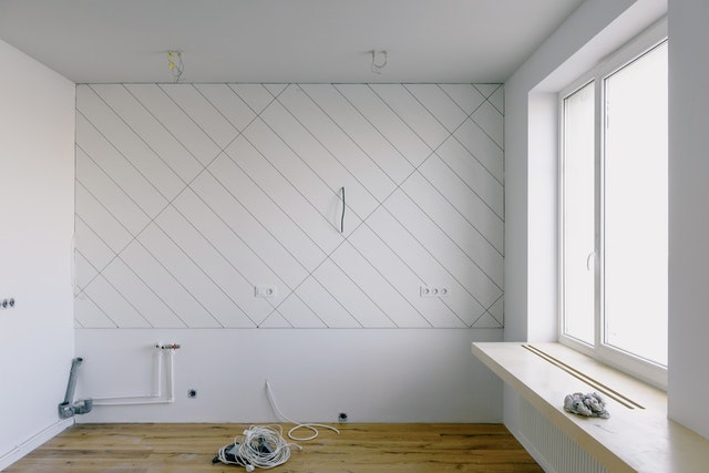
- Run 12-gauge NM electrical cable from the service panel (power source) to the timer box. Attach the cable to the box with a cable clamp, leaving 8” of extra cable extending from the box. Drill a 5/8” hole through the center of the stud, about 12” above the boxes. Run a short branch cable from the timer box to the thermostat box, securing both ends with clamps. The branch cable should make a smooth curve where it passes through the stud.
- Vacuum the floor thoroughly. Plan the ceramic tile layout and snap reference lines for the tile installation. Spread the heating mats onto the floor with the power leads closest to the electrical boxes. Position the mats 3” to 6” away from walls, showers, bathtubs, and toilet flanges. You can lay the mats into the kick space of a vanity but not under the vanity cabinet or over expansion joints in the concrete slab. Set the edges of the mats close together, but do not overlap them: The heating wires in one mat must be at least 2” from the wires in the neighbouring mat.
- Confirm that the power leads still reach the thermostat box. Then, secure the mats to the floor using strips of double-sided tape spaced every 24”. Make sure the mats are lying flat with no wrinkles or ripples. Press down firmly to secure the mats to the tape.
- Create recesses in the floor for the connections between the power leads and the heating-mat wires, using a grinder or a cold chisel and hammer. These insulated connections are too thick to lay under the tile and must be recessed to within 1/8” of the floor. Clean away any debris, and secure the connections in the recesses with a bead of hot glue.
- Thread a steel fish tape down one of the conduits, and attach the ends of the power leads to the fish tape, using electrical tape. Pull the fish tape and leads up through the conduit. Disconnect the fish tape, and secure the leads to the box with insulated cable clamps. Cut off the excess from the leads, leaving 8” extending from the clamps.
- Feed the heat sensor wire down through the remaining conduit and weave it into the mesh of the nearest mat. Use dabs of hot glue to secure the sensor wire directly between two blue resistance wires, extending it 6” to 12” into the mat. Test the resistance of the heating mats with a multi-tester to make sure the resistance wires have not been damaged. Record the reading.
- 11. Install the ceramic floor tile. Use thin-set mortar as an adhesive, and spread it carefully over the floor and mats with a 3/8 “x ¼” square-notched trowel. Check the resistance of the mats periodically during the tile installation. If a mat becomes damaged, clean up any exposed mortar and contact the manufacturer. When the installation is complete, check the resistance of the mats once again and record the reading.
- Install an adapter cover (mud ring) to the thermostat box, then patch the wall opening with drywall. Complete the wiring connections for the thermostat and timer, following the manufacturer’s instructions. Attach the sensor wire to the thermostat setscrew connection. Apply the man-facture’s wiring labels to the thermostat box and service panel. Mount the thermostat and timer. Complete the circuit connection at the service panel or branch connection. After the flooring materials have fully cured, test the system.